LEDs
Hardware
The Romi has three small LED lights that you can control with your code.
These LED’s are considered digital channels, specifically digital outputs.
These means that you can set them to one of two states: true or false.
The FTC Romi app already provides names for these devices to use in your code.
The green LED is "dio_1", the red is "dio_2", and the yellow is "dio_3".
If you are using Blocks, you can already access these devices through the toolbox on left when writing code!
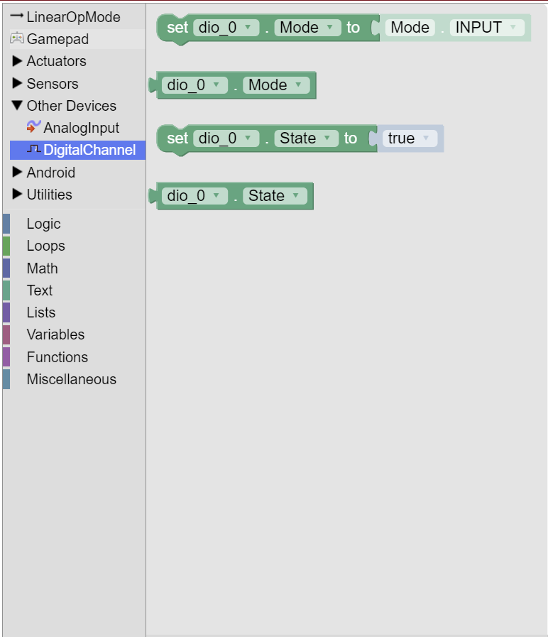
If you are using Java, you will need to get these devices from the HardwareMap in order to use them.
Add the highlighted code in the “init” section of your code (right after public void runOpMode())
public void runOpMode() {
    DigitalChannel dio_1 = hardwareMap.get(DigitalChannel.class, "dio_1");
    DigitalChannel dio_2 = hardwareMap.get(DigitalChannel.class, "dio_2");
    DigitalChannel dio_3 = hardwareMap.get(DigitalChannel.class, "dio_3");
    // ...rest of init code...
    waitForStart();
    // ...rest of run code...
}
Configuration
In order to use these digital channels as outputs, we have to configure them as such in the init section of our code.
We can do this with setMode:
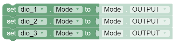
dio_1.setMode(DigitalChannel.Mode.OUTPUT);
dio_2.setMode(DigitalChannel.Mode.OUTPUT);
dio_3.setMode(DigitalChannel.Mode.OUTPUT);
Turning the Lights On
The LED devices are digital outputs, meaning that you can set them to one of two states: true or false.
As you may expect, setting the channel to true turns the LED on, and setting it to false turns it off.
We can control a digital output’s state by using setState
By default, all the channels are set to false (LED off). Let’s check that the LED devices are working
by setting all their states to true in the loop section of our code:
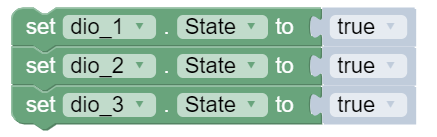
dio_1.setState(true);
dio_2.setState(true);
dio_3.setState(true);
Running this code should cause the three LED’s to turn light up on the Romi!
Light Show
Now we can do something more complicated with the LED’s. Let’s make it so that each LED turns on individually, with a short delay in between.
We can use the sleep(ms) function to create a delay in our code.
ms is the number of milliseconds we should delay for.
1000 milliseconds = 1 second, so if you wanted to delay for a half second for example, you would write sleep(500).
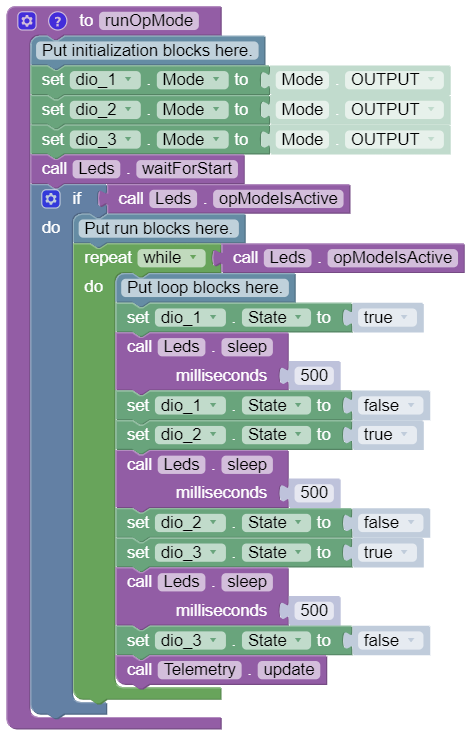
Replace your loop code with the following code:
You can grab the sleep block from the LinearOpMode tab of the toolbox.
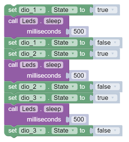
dio_1.setState(true);
sleep(500);
dio_1.setState(false);
dio_2.setState(true);
sleep(500);
dio_2.setState(false);
dio_3.setState(true);
sleep(500);
dio_3.setState(false);
Full Code
package org.firstinspires.ftc.teamcode;

import com.qualcomm.robotcore.eventloop.opmode.LinearOpMode;
import com.qualcomm.robotcore.eventloop.opmode.TeleOp;
import com.qualcomm.robotcore.hardware.DigitalChannel;

@TeleOp(name = "Leds")
public class Leds extends LinearOpMode {
  /**
   * This function is executed when this Op Mode is selected from the Driver Station.
   */
  @Override
  public void runOpMode() {
    DigitalChannel dio_1 = hardwareMap.get(DigitalChannel.class, "dio_1");
    DigitalChannel dio_2 = hardwareMap.get(DigitalChannel.class, "dio_2");
    DigitalChannel dio_3 = hardwareMap.get(DigitalChannel.class, "dio_3");

    // Put initialization blocks here.
    dio_1.setMode(DigitalChannel.Mode.OUTPUT);
    dio_2.setMode(DigitalChannel.Mode.OUTPUT);
    dio_3.setMode(DigitalChannel.Mode.OUTPUT);
    waitForStart();
    if (opModeIsActive()) {
      // Put run blocks here.
      while (opModeIsActive()) {
        // Put loop blocks here.
        dio_1.setState(true);
        sleep(500);
        dio_1.setState(false);
        dio_2.setState(true);
        sleep(500);
        dio_2.setState(false);
        dio_3.setState(true);
        sleep(500);
        dio_3.setState(false);
        telemetry.update();
      }
    }
  }
}